

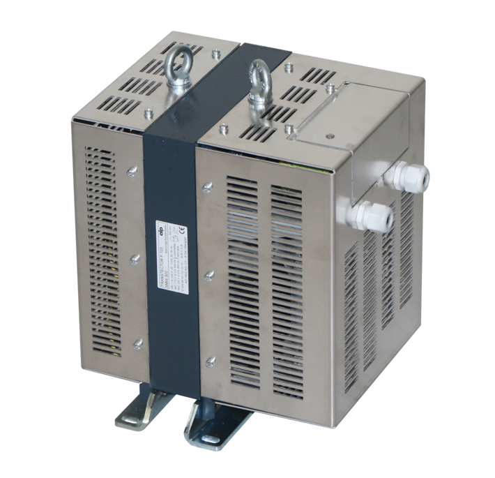
Magnetic stabilizers
The Magnetic Stabilizer as an Integral Protection Element Against Disturbances
Magnetic stabilizers, also known as magnetic voltage regulators, often lead a "shadowy existence." They are installed somewhere inside the control cabinet of a system or machine, and nobody pays them much attention. In most cases, it was not the development and design engineers who brought about their installation, but rather the service department—often after a succession of difficult-to-reproduce errors had occurred, leading to high costs.
The Current State of the Art
A powerful argument for using magnetic stabilizers is their reliability and service life, which are unmatched by any other device. Today's stabilizer consists of just two components—an inductor and a capacitor—and is also inherently short-circuit proof due to its very design.
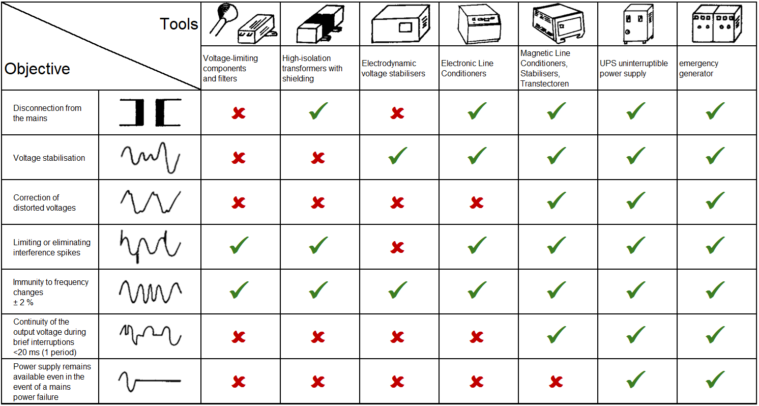
Furthermore, in terms of versatility, it is outperformed by only two categories of equipment: electronic UPS devices and rotary motor-generator sets, both of which, however, have significantly lower MTBF values and are not maintenance-free. The following table lists all major types of disturbances along with the primary remedies used.
EMC, magnetic stabilisers as filters and protective components
Magnetic stabilisers possess a whole range of properties that are unique in this combination. This is primarily due to the resonant circuit. This acts as an energy store, bridging short interruptions in the mains supply on the one hand, and absorbing high-energy interference spikes on the other.
Furthermore, through geometric arrangement and/or shielding, the designer can reduce the coupling capacitance between the primary and secondary sides to such an extent that even very fast interference spikes are attenuated by 40 to 120 dB. This means a reduction in the interference level to between 1/100 and 1/1,000,000. ‘Normal’ stabilisers operate at 50 to 60 dB. This corresponds to a capacitance of approximately 5 pF for medium-power stabilisers. From a guaranteed 100 dB upwards, the effort required for shielding becomes quite substantial, and measures regarding the supply cables are also essential on the user’s side.
Design
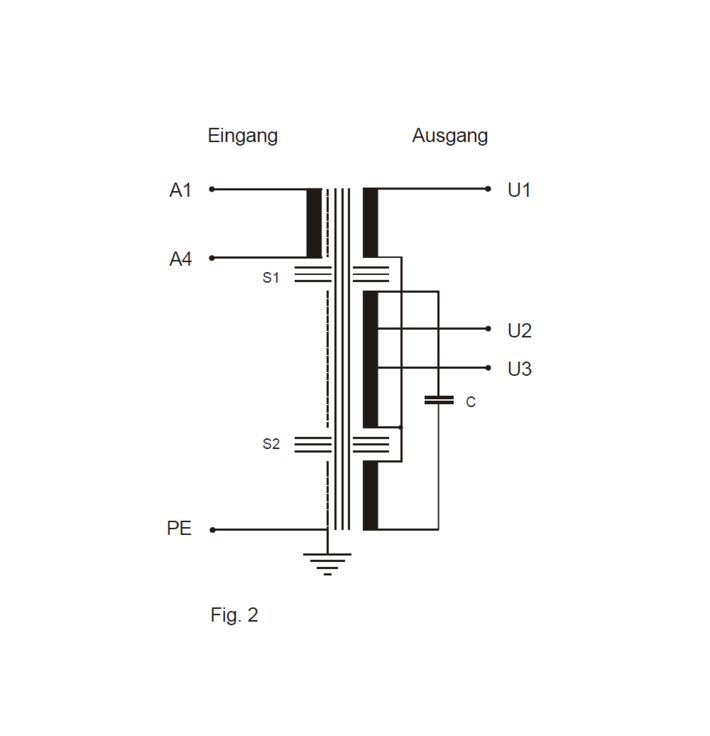
Nowadays, almost all magnetic stabilisers are arranged on a single iron core. The arrangement shown here in Fig. 2 is based on a design in which the primary side is coupled to the secondary side only very ‘loosely’ via magnetic shunts.
A common feature of all magnetic stabilisers is the parallel resonant circuit, tuned to the mains frequency, formed by the capacitor C and an inductor. However, the arrangement of this circuit varies depending on the manufacturer.
In the example shown in Fig. 2, it consists of the winding on the centre leg and the capacitor. This causes the centre section to saturate. The lowest winding, together with the capacitor, serves as a blocking circuit for the third harmonic – i.e. 150 Hz at 50 Hz. The uppermost winding, located on the same leg as the primary winding, compensates for voltage drops caused by load changes.